

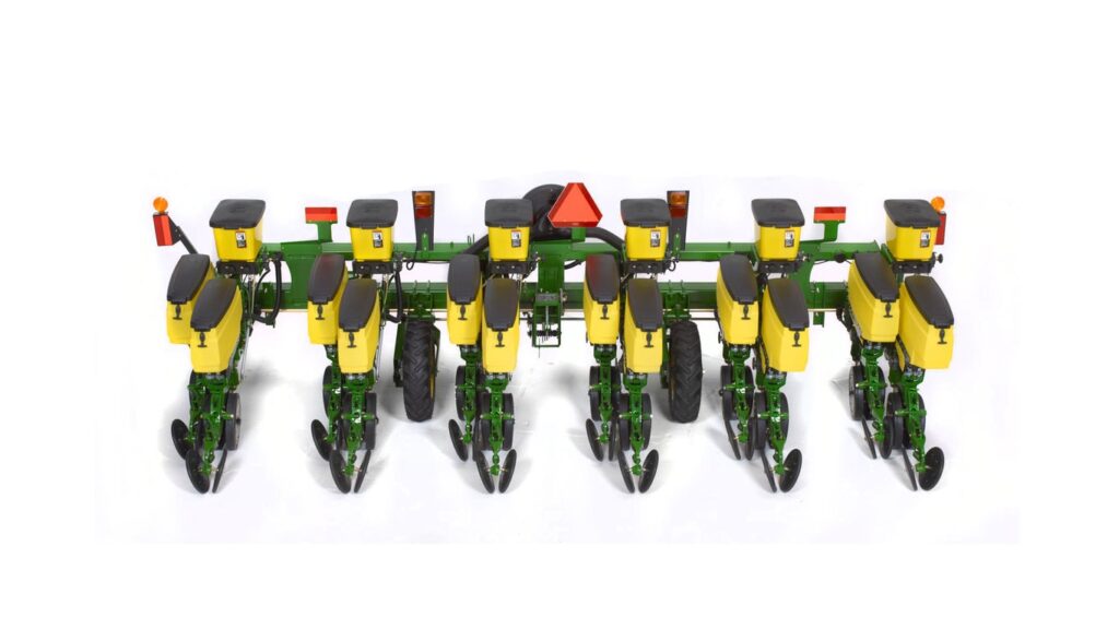
John Deere 1705 Twin Row Planter
Agriculture
- 6 twin rows with 36-in (91-cm) or 38-in (96-cm) spacing
- Available in 2-bu. twin row MaxEmerge™ 5 row unit
- Optional lift assist wheels may be ordered
Featured List
- Spacing (inches): 36-in (91-cm) or 38-in (96-cm) spacing
- Transport Width: 13 ft. 3 in., 16 ft. 4 in., 23 ft. 1 in., 28 ft. 10 in.
- Central Commodity System (CCS): N/A
- Row Unit: MaxEmerge 5
- Number of Rows: 6 twin rows
Featured Content
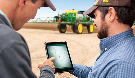
Connected Support technology
When you buy John Deere equipment, you expect reliability. You also know that problems can happen, and a product is only as good as the support behind it. That’s why John Deere equipment is prepared with technology that senses potential issues and can alert you and your dealer promptly—in the cab or anywhere you are.
John Deere Connected Support is a revolutionary change to support that leverages technology and the connectivity of JDLink™ telematics to prevent downtime and resolve problems faster. These tools decrease downtime by an average of 20 percent, enabling faster responses to unexpected problems and reducing technician trips to your machine. For some issues, unplanned downtime can even be prevented altogether through prediction of the issue.
With your permission, John Deere Connected Support:
-
- Keeps you running by monitoring machine health and promptly alerting you and your dealer of issues
-
- Saves time by remotely viewing in-cab displays, reducing trips to the machine
-
- Reduces or even eliminates technician trips to a machine through remote diagnostic and remote software reprogramming capabilities
-
- Connects experts with the information needed to respond to downtime faster and prevent it altogether
With more than a decade of experience leveraging connectivity to solve problems, no one else has the experience, tools, and knowledge to keep you running as John Deere and your John Deere dealer can. Connected Support is an in-base feature on all John Deere products with factory- or field-installed JDLink.
Seed variable-rate drive provides the ultimate planting productivity by utilizing one, two, or three hydraulic motors (varies by model) to turn the seeding drive shaft. Hydraulic control of the seeding drive allows for on-the-go seeding rate changes right from the display mounted inside the tractor cab. Combine this seeding flexibility with the map-based planting option, and seeding rates adjust automatically based on the prescribed map.
Variable-rate drive offers the following advantages over common, ground, or contact-tire drive systems:
-
-
Rate changes are almost instantaneous; no ramp up or ramp down of system as in some competitive systems
-
-
- Permits the producer to match seed population based on different soil types or irrigation practices
-
- John Deere design provides added operator safety by eliminating any possible drive creep found in some competitive variable-rate drive systems
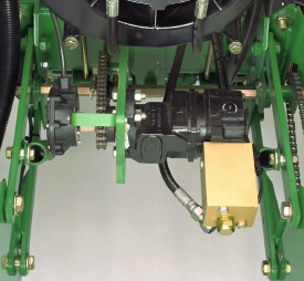
1755 equipped with variable-rate drive
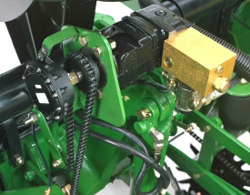
1765NT equipped with variable-rate drive
Single- or dual-motor systems for variable-rate drives are available for all John Deere planters except the 1785 Rigid Frame. Variable-rate drive is available as a factory-installed option for all applicable planter models.
Single- or dual-motor systems are available as field-installed attachments for most planter models; however, a three-motor variable-rate drive field-installed attachment is not available.
Seed variable-rate drive requires the SeedStar™ monitor and a radar input signal. Either tractor or planter radar may be used. Planter radar is ordered separately.
NOTE: Peanut seed meter disks require the variable-drive transmission.
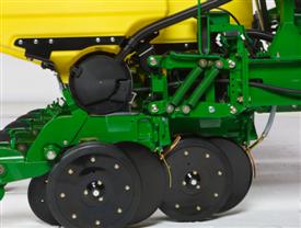
Pneumatic downforce springs

Pneumatic downforce system
Pneumatic downforce provides convenient, simple adjustment of downforce for the whole planter from one location. The amount of downforce applied is infinitely adjustable from 0 kg to 181.4 kg (0 lb to 400 lb). Pneumatic downforce provides more consistent downforce throughout the range of row-unit travel than mechanical-spring downforce systems. Each row-unit has a single rubber air bag located between the parallel arms. The air bags are hooked in parallel so that air can be added or released from all rows at once from one location.
Pneumatic downforce systems are available as base equipment on all 1705 Series and DB Planters.
Pneumatic downforce with spring upforce kit
Pneumatic downforce with spring upforce kit
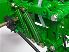
Spring upforce kit
Pneumatic downforce with spring upforce kit option includes the same convenient, simple adjustment of downforce with up to 81.6 kg (180 lb) of upforce per row-unit. Dual upforce springs provide the row-unit upforce to increase flotation in softer soils. This upforce can also be used to counteract excess row-unit margin or extra weight cause by seed, tillage, or other attachments on the row-unit. Upforce springs will limit the maximum amount of downforce that can be placed on a row-unit by the downforce system and should only be used in conditions were adequate and consistent depth control is easily maintained.
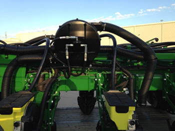
Vacuum system
Vacuum blower assembly
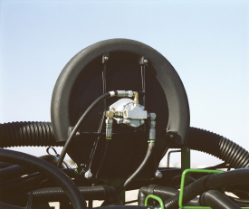
Vacuum blower shown on 1795
Vacuum is created by a hydraulically driven vacuum blower assembly mounted on the planter frame. The vacuum blower requires a tractor with a closed-center hydraulic system and a separate selective control valve (SCV). For tractors with open-center hydraulic system, a vacuum 540-rpm or 1000-rpm power take-off (PTO) driven hydraulic pump system is available. PTO pumps offered from the factory are limited to 15-row applications or less.
Different vacuum levels are required depending on the crop being planted. A hydraulic control valve lets the operator regulate vacuum blower speed, changing the vacuum level. On late-model John Deere tractors, vacuum levels are set from the tractor seat using the SCV controls. The control valve is not needed in those applications. At full flow, the system flows up to 18.9 L/min (5 gpm) per motor.
Convenient vacuum gauges located on the planter hitch give a visual indication of the vacuum level. When using a SeedStar™ monitor, the vacuum level can be displayed on the monitor. Consult the vacuum metering seed charts in the operator’s manual for initial vacuum setting recommendations.
Vacuum meter case drain
Case drain coupler 7000 Series Tractor
All planters with vacuum metering systems have case drain motors on the vacuum blowers. Case drain lines will have a flush-face case drain coupler on the planter and will require a corresponding flush-face case drain coupler on the tractor. The flush-face coupler simplifies implement attachment by allowing operators to easily identify the case drain. The unique hose tip is unable to connect to another coupler on the tractor, ensuring the correct setup.
It is important to connect this case drain hose to prevent the continuous and complete draining of hydraulic fluid due to the relief feature that opens the coupler when the pressure reaches 68.9 kPa (10 psi). This relief feature is designed to protect the motor shaft seal if for any reason the case drain hose was not connected to the tractor. The flush-face hose tips have less back pressure than ISO case drain tips, and the flat surface makes these couplers easy to clean, providing less chance for contamination.
The case drain line is also used with all Central Commodity System (CCS™) fan motors.
| Drive System - Base | Ground driven or hydraulic driven |
|---|---|
| Lift System - Type | Integral or Semi-integral |
| Markers - Type | Automatic alternating or independent control |
| Key Specs - Number of rows | 6 twin rows |
| Rows and Row Spacing - Number of rows | 6 twin rows |
| Seed Meters - Base | Vacuum |
| Frame - Flexibility | None |
| Frame - Fold configuration | Figid |
| Row Units - Opener | Tru-Vee Double Disk |
| Key Specs - Row unit seed hoppers | Capacity 58 or 106 L 1.6 or 3 bu |
| Markers - Control | |
| Row Units - Seed tube sensors | Optional -- |
| Dimensions - Transport width (with markers) | 5.9 m 19.25 in. |
| Row Units - Scrapers, opener blades | |
| Key Specs - Frame - Flexibility | None |
| Fertilizer - Fertilizer opener type | |
| Row Units - Row unit seed hoppers | Capacity 58 or 106 L 1.6 or 3 bu |
| Key Specs - Row spacing | 91 or 96 cm 36 or 38 in. |
| Markers - Marker disk | |
| Row Units - Type | MaxEmerge™ 5 row unit |
| Tires - Base | 7.60-15 6 Ply - Traction: 280 kPa 2.8 bar (40 psi) 7.60-15 8 Ply - Traction: 359 kPa 3.6 bar (52 psi) |
| Additional Information - Recommended tractor hydraulics | Hydraulic oil required to operate the planter: 5.7 L 1.5 gal. Hydraulic system working pressure: 20,684 kPa 207 bar (3000 psi) Hydraulic system burst pressure: 82,737 kPa 827 bar (12,000 psi) |
| Fertilizer - Dry fertilizer | |
| Key Specs - Frame - Fold configuration | Rigid |
| Seed Meters - Central Commodity System | |
| Dimensions - Transport height | 2.4 m 8 ft |
| Row Units - Row unit down force | |
| Closing System - Rubber tire closing system | |
| Key Specs - Seed Meters | Base Vacuum |
| Rows and Row Spacing - Row spacing | 91 or 96 cm 36 or 38 in. |
| Closing System - Cast iron closing system |