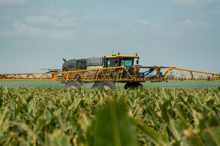
STS14 Hagie™ Self-Propelled Sprayer
- John Deere
- Agriculture
Find Your Nearest Location
Key Features & Specs
- Full-season crop protection and nutrient management capability
- Handle hills with ease with John Deere 300-hp engine with high-performance cooling package
- Reduce compaction with a lightweight, balanced machine design
- Avoid crop damage with 72-in. (183cm) ground clearance with standard tires
- Use information with John Deere Integrated Technologies
- Engine hp 300 (221 kW)
- Solution Capacity 1,400 gallons (5,300 L)
- Boom Sections 9
- Application Speed 20 mph (32 km/h)
- Transport Speed 35 mph (56 km/h)
- Boom Width up to 120 feet (36.6 m)
- + Expand All
- - Close All
-
John Deere Connected Support™ prevents downtime and efficiently resolves issues with revolutionary technology-based solutions
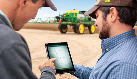 Connected Support technology
When you buy John Deere equipment, you expect reliability. You also know that problems can happen, and a product is only as good as the support behind it. That’s why John Deere equipment is prepared with technology that senses potential issues and can alert you and your dealer promptly—in the cab or anywhere you are.
John Deere Connected Support is a revolutionary change to support that leverages technology and the connectivity of JDLink™ telematics to prevent downtime and resolve problems faster. These tools decrease downtime by an average of 20 percent, enabling faster responses to unexpected problems and reducing technician trips to your machine. For some issues, unplanned downtime can even be prevented altogether through prediction of the issue.
With your permission, John Deere Connected Support:- Keeps you running by monitoring machine health and promptly alerting you and your dealer of issues
- Saves time by remotely viewing in-cab displays, reducing trips to the machine
- Reduces or even eliminates technician trips to a machine through remote diagnostic and remote software reprogramming capabilities
- Connects experts with the information needed to respond to downtime faster and prevent it altogether
With more than a decade of experience leveraging connectivity to solve problems, no one else has the experience, tools, and knowledge to keep you running as John Deere and your John Deere dealer can. Connected Support is an in-base feature on all John Deere products with factory- or field-installed JDLink.
-
Hagie™ STS14 engine
9.0-L (549-cu in.) Final Tier 4 (FT4) John Deere engine
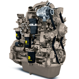 PowerTech™ PSS 9.0-L (549-cu in.) John Deere diesel engine
The Hagie STS14 is powered by the PowerTech PSS 9.0-L (549-cu in.) John Deere diesel engine, which is offered in a 246-kW (330-hp) FT4 configuration.
These turbocharged, air-to-air aspirated engines deliver consistent power over a wide range of engine speeds (rpm) with a power bulge rated speed to provide excellent torque in demanding applications.
Hagie is a trademark of Hagie Manufacturing Company, LLC and similar to John Deere branded equipment, John Deere will also support Hagie equipment.
-
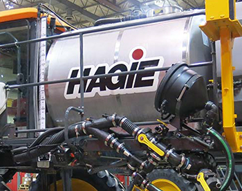
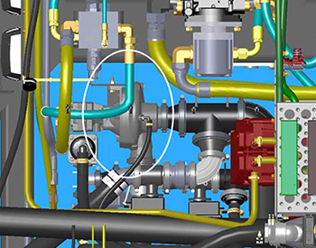
Solution tank, pump, and pump switch
The solution system is a constantly monitored, continuously adjusted, computer-controlled system. The cab-mounted digital spray system console receives information from various inputs to help determine L/ha (gpa) and L/min (gpm).
Solution tank
 Solution tank
Sprayer model Tank capacity Tank type STS10 3785 L (1000 gal.) Stainless-steel tank STS12 4542 L (1200 gal.) Stainless-steel tank STS14 5299 L (1400 gal.) Stainless-steel tank STS16 6056 L (1600 gal.) Stainless-steel tank Solution pump
 Solution pump
The Hypro® 9306C-HM1C-BU solution pump (located beneath center of machine) is a centrifugal-type, hydraulically-driven pump that is controlled by the solution pump control valve and the spray system console. It comes with silicon-carbide seals, 7.6-cm (3-in.) inlet plumbing and 5.1-cm (2-in.) outlet plumbing.
The solution pump draws solution out of the tank at the rate determined during calibration. It dispenses solution through the many valves and hoses that make up the spray system and also dispenses fluids through the agitation and rinse systems.
Solution pump switch
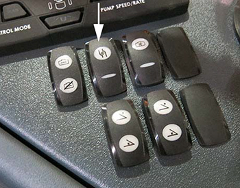 Solution pump switch
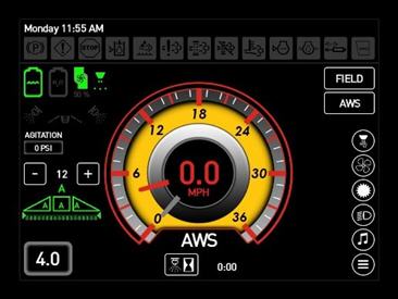 Machine control display - Home
The solution pump switch is located on the side console and is used to turn the solution pump on and off.
NOTE: When the solution pump is on, a solution pump indicator (located on the machine display home page - field mode) will be illuminated.Hypro is a trademark of Pentair Flow Technologies, LLC.
-
Frame and axles
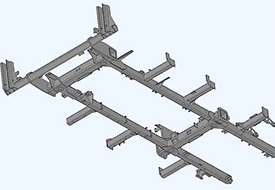 Chassis mainframe
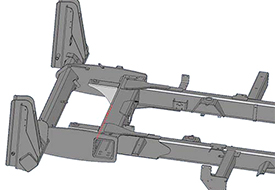 Horizontal cross-through axle tube
The STS Series mainframe design features horizontal cross-through axle tubes, as well as boom and platform mounts on weldment.
- 144.8-cm (57-in.) mainframe width (from outside of each mainframe tube)
- 301-cm (118.5-in.) mainframe width (from outside of each boom cradle weldment)
- 183-cm (72-in.) ground clearance
-
STS Series hybrid spray booms
 STS Series Sprayer booms
The spray booms are controlled by an electrohydraulic system. This system consists of operator-manipulated switches (located on the side console and the hydrostatic drive control handle) and hydraulic cylinders (attached to the booms), which provide lift, level, and horizontal extension. Hybrid booms are available in widths of 27.4 m, 30.5 m, 36.6 m, and 40.2 m (90 ft, 100 ft, 120 ft, and 132 ft).
The spray booms are offered in a variety of configurations depending on the model and the producer's application needs.27.4-m (90-ft) boom with 38.1-cm (15-in.) row spacing
Numerical values key:
- Section one
- Section two
- Section three
- Section four
- Section five
- Section six
- Section seven
Alphabetical values key:
- 18.3-m (60-ft) 24-row planter
- 9.1-m (30-ft) 12-row planter
- 9.1-m (30-ft) 12-row planter
- 9.1-m (30-ft) 12-row planter
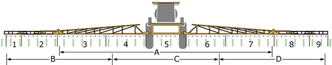
30.5-m (100-ft) boom with 38.1-cm (15-in.) row spacing
Numerical values key:
- Section one
- Section two
- Section three
- Section four
- Section five
- Section six
- Section seven
- Section eight
- Section nine
Alphabetical values key:
- 18.3-m (60-ft) 24-row planter
- 3.05 m (10 ft)
- 9.1-m (30-ft) 12-row planter
- 9.1-m (30-ft) 12-row planter
- 9.1-m (30-ft) 12-row planter
- 3.05 m (10 ft)
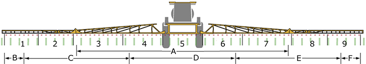
36.6-m (120-ft) boom with 38.1-cm (15-in.) row spacing
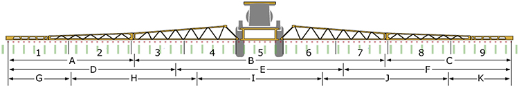
Numerical values key:
- Section one
- Section two
- Section three
- Section four
- Section five
- Section six
- Section seven
- Section eight
- Section nine
Alphabetical values key:
- 9.1 m (30 ft)
- 18.3-m (60-ft) 24-row planter
- 9.1 m (30 ft)
- 9.1-m (30-ft) 16-row planter
- 9.1-m (30-ft) 16-row planter
- 9.1-m (30-ft) 16-row planter
- 4.6 m (15 ft)
- 9.1-m (30-ft) 12-row planter
- 9.1-m (30-ft) 12-row planter
- 9.1-m (30-ft) 12-row planter
- 4.6 m (15 ft)
Boom configurations
Hybrid boom width Boom
locationNumber of sections Wet boom nozzle
spacing27.4 m (90 ft) Front Seven
38 or 51 cm
(15 or 20 in.)30.5 m (100 ft) Front Nine
38 or 51 cm
(15 or 20 in.)36.6 m (120 ft) Front Nine
38 or 51 cm
(15 or 20 in.)40.2 m (132 ft) Front Nine
38, 51, or 56 cm
(15, 20, or 22 in.)Materials used in boom construction:
- 27.4-m, 30.5-m, 36.6-m, and 40.2-m (90-ft, 100-ft, 120-ft, and 132-ft) booms – steel/aluminum hybrid
Boom
| Plumbing material | Stainless steel |
| Ground height adjustment | 46 to 264 cm 18 to 104 in. |
| Boom sections | 7 or 9 sections on booms - 27/36 m 90/120 ft |
| Breakaway width | For 27-m (90-ft) booms - 3 m 10 ft For 30-m (100-ft) booms - 3.8 m 12.5 ft For 36-m (120-ft) booms - 4.6 m 15 ft |
| Boom length options | 18/24/27, 18/30, or 36/40 m 60/80/90, 60/100, or 120/132 ft |
Chassis
| Dry compatible | No |
| Suspension | Independent air-ride |
| Front tires | 380/85R46, 320/90R50, or 320/105R54 |
| Rear tires | 380/85R46, 320/90R50, or 320/105R54 |
| Flotation tires | LSW 680/55R42 |
| Hydraulic tread adjust | Optional |
| Parking brake | Integrated in final drives |
| Primary brakes | Drive system dynamic braking |
| Ladder raise/lower | Hydraulic |
| Total weight with 90-ft boom | 13,274 kg 29,266 lb |
| Crop clearance with standard tires | 183 cm 72 in. |
| Wheel tread spacing | 305 to 386 cm 120 to 152 in. |
| Wheel base | 422 cm 166 in. |
| Total weight with 120-ft boom | 13,156 kg 29,006 lb |
| Turning radius | 7 m 23 ft |
Drivetrain
| Type | Hydrostatic |
| Drive | Full-time four-wheel drive (4WD) |
| Shifting | Infinitely variable |
| Spray speed range | 0.8 to 32 km/h 0.5 to 20 mph |
| Hydraulic reservoir capacity | 190 L 50 gal. |
| Transport speed, maximum | 56 km/h 35 mph |
Engine
| Make | John Deere |
| Emissions | Final Tier 4 (FT4) |
| Number of cylinders | Six |
| Alternator | 240 amp |
| Diesel exhaust fluid (DEF) tank capacity | 37.9 L 10 gal. |
| Fuel tank capacity | 510 L 135 gal. |
| Displacement | 9 L 548 cu in. |
| Peak rated power | 224 kW 300 hp |
Key Specs
| Suspension | Independent air-ride |
| Total weight with widest boom | 13,156 kg 29,006 lb |
| Spray speed range | 0.8 to 32 km/h 0.5 to 20 mph |
| Solution system - Capacity | 5000 L 1400 gal. |
| Crop clearance with standard tires | 183 cm 72 in. |
| Transport speed, maximum | 56 km/h 35 mph |
| Engine | Peak rated power 224 kW 300 hp |
| Boom length options/Material | 18/24/27, 18/30, or 36/40 m 60/80/90, 60/100, or 120/132 ft |
| Rinse tank capacity | 378.5 L 100 gal. |
Options
| Air compressor | Onboard air |
| Foam marker capacity | 12 L 3 gal. |
Solution system
| Tank material | Stainless steel |
| Automatic section control | Optional |
| Solution system control | John Deere |
| Chemical injection method | Raven Sidekick - optional |
| Chemical eductor | Optional |
| Pressure strainer | 50 mesh |
| Boom strainer | Standard 80 mesh |
| Rinse tank capacity | 378.5 L 100 gal. |
| Chemical eductor capacity (size) | 30 L 8 gal. |
| Quick fill size | 7.6 cm 3 in. |
| Fill location | Front standard Side/rear optional |
| Flow meter size | 5.8 cm 2 in. |
| Capacity | 5000 L 1400 gal. |
Additional information
| Date collected | 14-Jun-2017 |