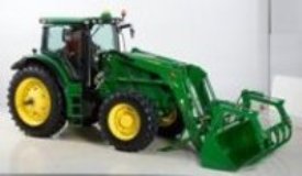
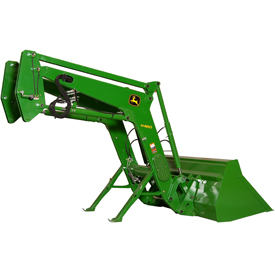
H310 Loader
- John Deere
- Agriculture
Key Features & Specs
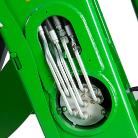
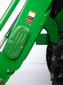
- Superior strength and visibility
- For heavy-duty chores
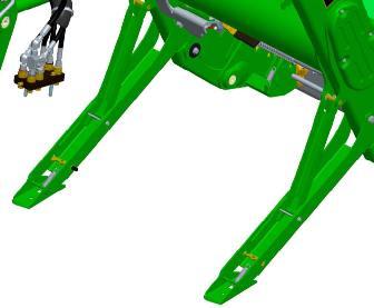
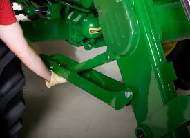
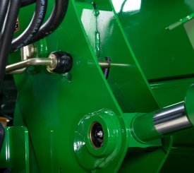
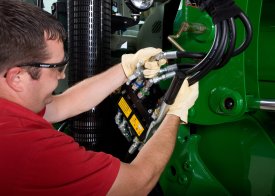
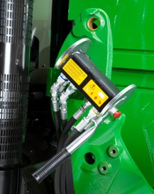
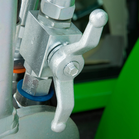
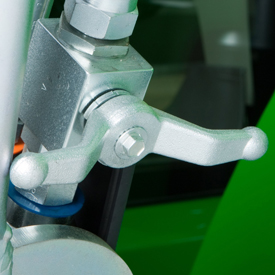
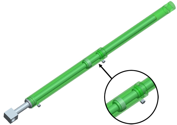
- Parking stands are integrated on the loader
- Lift Capacity NSL: 3,104-3,236 pounds (1408-1468 kg) MSL: 3,891-4,085 pounds (1765-1853 kg)
- Lift Height NSL: 148.8-152.8 in. (3.782-3.881 m) MSL: 148-153 in (3.759-3.886 m)


Loader
| Leveling configuration | Mechanical Self Leveling (MSL) |
| Bucket used | Materials 73 in. Materials 1850 mm |
| Bucket weight | 503 lb 228 kg |
| Lift capacity at full height | Measured at pivot (U) 3746 lb 1699 kgMeasured at 800 mm ahead of pivot (V) 1846 kg 4070 lb |
| Lift capacity at 59 in. (1500 mm) | Measured at pivot (W) 2187 kg 4822 lbMeasured at 800 mm ahead of pivot (X) 2090 kg 4608 lb |
| Boom breakout force | Measured at pivot (Y) 2677 kgf 5902 lbfMeasured at 800 mm ahead of pivot (Z) 2335 kgf 5148 lbf |
| Bucket rollback force capacity | At maximum height (VV) 1513 kgf 3336 lbfAt 59-in. (1500-mm) lift height (XX) 3003 kgf 6620 lbfAt ground-level line (ZZ) 3059 kgf 6744 lbf |
| Dimensions | Maximum lift height (A) 3855 mm 151.8 in.At full height - bucket level(B) 3661 mm 144.1 in.At full height - bucket dumped (C) 2826 mm 111.3 in. |
| Overall length (I+F), ft (m) | 5 m 16.4 ft |
| Digging depth (H) | 31 mm 1.2 in. |
| Reach | At maximum height (D) 800 mm 31.5 in.At ground level - bucket level (F) 2422 mm 95.4 in. |
| Bucket angle | Dump angle, degrees (E) -7 degree (angle)Rollback angle, degrees (G) 42 degree (angle)Dump angle, ground -95 degree (angle) |
| Cycle times | Loader raise, seconds 2.3 secondsLoader lower, seconds 1.9 secondsBucket dump, seconds 1.4 secondsBucket rollback, seconds 1.4 seconds |