660R Loader
- John Deere
- Agriculture
Key Features & Specs
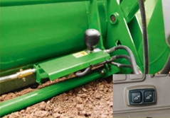
- Tool-free removal and attachment with just a few, simple steps
- Frame design that allows for maximum maneuverability
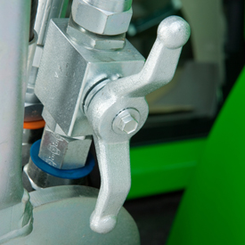
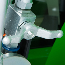
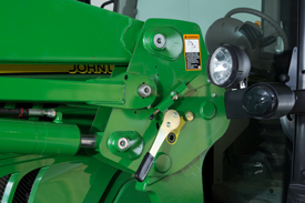
- Automatic Mast Latch system for quick change from loader to three-point implements
- Repositioned leveling links for better visibility
- Lift Capacity 5,701 pounds (2586 kg)
- Lift Height 178 in. (4.52 m)


Loader
| Leveling configuration | Non-Self Leveling (NSL) |
| Bucket used | Heavy-duty grapple 2150 mm Heavy-duty grapple 85 in. |
| Bucket weight | 327 kg 721 lb |
| Lift capacity at full height | Measured at pivot (U) 2564 kg 5663 lbMeasured at 800 mm ahead of pivot (V) 1861 kg 4103 lb |
| Lift capacity at 59 in. (1500 mm) | Measured at pivot (W) 2800 kg 6173 lbMeasured at 800 mm ahead of pivot (X) 2222 kg 4899 lb |
| Boom breakout force | Measured at pivot (Y) 2958 kgf 6521 lbfMeasured at 800 mm ahead of pivot (Z) 2237 kgf 4932 lbf |
| Bucket rollback force capacity | At maximum height (VV) 2916 kgf 6429 lbfAt 59-in. (1500-mm) lift height (XX) 4601 kgf 10143 lbfAt ground-level line (ZZ) 4505 kgf 9932 lbf |
| Dimensions | Maximum lift height (A) 4495 mm 177 in.At full height - bucket level(B) 4255 mm 168 in.At full height - bucket dumped (C) 3481 mm 137 in. |
| Overall length (I+F), ft (m) | 5.6 m 18.4 ft |
| Digging depth (H) | 81 mm 3 in. |
| Reach | At maximum height (D) 1038 mm 41 in.At ground level - bucket level (F) 2848 mm 112 in. |
| Bucket angle | Dump angle, degrees (E) 60 degree (angle)Rollback angle, degrees (G) 48 degree (angle)Dump angle, ground 146 degree (angle) |
| Cycle times | Loader raise, seconds 3.98 secondsLoader lower, seconds 2.75 secondsBucket dump, seconds 2.65 secondsBucket rollback, seconds 1.81 seconds |