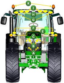
Lights on the 6R Series Tractors have been positioned and designed to provide maximum visibility to the front, sides, and rear of the tractor to increase productivity in any operating condition. The cab lighting pattern provides 330 degrees of coverage while the hood lighting provides the remaining 30 degrees for completely programmable, 360-degree, stadium-style lighting.
Base lighting
Two HB3 hood road lights - low beam (A)
Two HB3 hood road lights - high beam (B)
Two HB3 hood outer work lights (C)
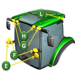
Turn signals beltline mounted with clearance lights (E)
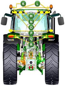
Turn signals fender mounted (Q)
Brake lights rear fender mounted (R)
Two HB3 halogen inner front-roof-mounted adjustable work lights (H) / with a panorama roof, the work light represented as (G)
Two HB3 halogen inner rear-roof-mounted adjustable work lights (N)
Code
Hood
Belt
Front roof
Side
Rear roof
Fender
A
B
C
F
E
G
H
K
I
L
N
O
M
P
Q
R
* Base package - with non-panorama roof
HB3
HB3
HB3
HB3
HB3
HB3
HB3
HB3
HB3
Light package - Standard
873F
HB3
HB3
HB3
HB3
HB3
LED
X
LED
HB3
HB3
HB3
HB3
HB3
HB3
Light package - Premium
873E
HB3
HB3
HB3
HB3
HB3
LED
X
LED
HB3
LED
HB3
HB3
HB3
HB3
Light package – Base panorama roof code (878W)
HB3
HB3
HB3
HB3
HB3
HB3
HB3
HB3
Light package - Standard - panorama roof
873A
HB3
HB3
HB3
HB3
HB3
LED
X
HB3
HB3
HB3
Lighting package – Panorama light package
873C
HB3
HB3
HB3
HB3
HB3
LED
X
HB3
LED
HB3
HB3
Lighting identification from front view of tractor
Lighting availability on panorama roof
Lighting identification from rear view of tractor
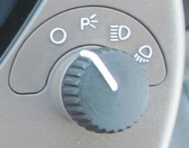
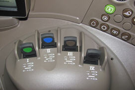
Selecting the lighting mode
Overview
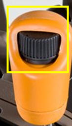
Operators can quickly select a lighting mode on the steering console by operating a rotary switch. The four settings available are:
Light switch in the off position
Headlights, taillights, and warning lights in the on position
Headlights in the on position
Headlights and work lights in the on position (depending on CommandCenter™ assignments)
Lighting control switch on dashboard
Benefits
Easy to locate and operate
Small and compact design
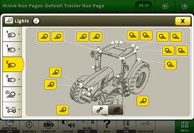
Programmable lighting
Overview
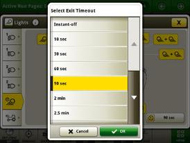
The CommandCenter allows operators to customize two different light programs. The operator can switch between the two programs with the push button. Also standard on the 6R Tractors is the battery power-saver feature.
When the engine is off and the outside lights have been left on, this feature is designed to avoid battery run-down. After the lights have been left on for 30 minutes and the key is in the off position, the lights will cycle, or blink on and off five times as an alert. The lights will continue to illuminate for one more minute and then automatically shut off to protect the battery.
CommandCenter programmable time out lighting
CommandCenter programmable lights page
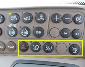
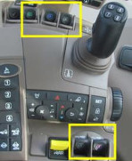
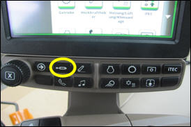
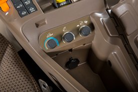
Beacon lights/hazard warning lights, work light 1 and 2 location on right-hand console
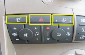
Beacon lights/hazard warning lights, work light 1 and 2 location on CommandCenter
Benefits
The John Deere light programming adds high performance to the operator.
Individual light selection adds to high operator performance to prevent blinding other operators when two machines are working close to each other.
Improved uptime due to 360-degree lighting.
Additional lights
Overview
Additional lighting is available to match various applications and ensure maximum around-the-clock productivity. Optional LED lighting technology provides extreme brightness and a daylight color output for excellent definition of the field.
The LED lights provide 40 percent greater coverage width and 10 percent more light coverage in the rear. LED lighting packages use 45 percent less amps than standard halogen lights and have an increased life expectancy over HID lights which leads to lower costs of ownership over the life of the tractor.
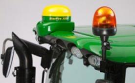
Beacon light for added visibility
Overview
One beacon light is mounted on the front of the cab to provide a rotating warning light for road traveling and added visibility.
Beacon light
Benefits
To warn other road users of the presence of a large machine on the road.
Easily removed, with no tools required, when approaching height restricted areas.
Waterproof to ensure good performance when required.
The beacon has a degree of flexible movement, and are not completely static, and can withstand the impact of objects such as tree branches.
Details
Front cab is roof mounted.
A second beacon light can be field installed on the right side of the cab roof.
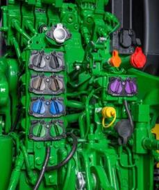
To control a rear implement, up to six SCVs or five SCVs plus Power Beyond can be ordered (6145R-6250R). For (6110R- 6130R) up to five SCVs or four SCVs plus Power Beyond can be ordered. The SCVs can be controlled electrically. Up to four mechanical SCVs are available, in combination with Power Beyond. All mechanical or electrical SCVs feature four positions - neutral, raise, lower, and float.
Benefits
Release levers make disconnecting hydraulic hoses easy
Relocated valves improve operator's visibility to the rear hitch
Up to six rear SCVs give operators total flexibility
Code
Description
Information
Availability
3312
Two mechanical SCVs – premium
Premium couplers with high-pressure relief lever. Two mechanical SCVs 450 Series. Only in combination with PowrQuad™ Plus transmission or AutoQuad™ Plus transmission. Only available on 6110R - 6130R.
6110R, 6120R, 6130R
3332
Three mechanical SCVs - premium
Premium couplers with high-pressure relief lever. Only in combination with PowrQuad Plus or AutoQuad Plus.
Premium couplers with high-pressure relief lever. When ordered with right-hand console, (code 2055) also electrical joystick (code 841L) for operation of rear SCVs or electrical midstack SCV (code 8922, 8923, 8914 or 8915) is required. A maximum of four SCVs can be operated via paddle pot at right-hand console.
Premium couplers with high-pressure relief lever. Not with right-hand console (code 2055). Not in combination with electrical joystick (code 841L) and any option with electrical joystick.
6145R, 6155R, 6175R, 6195R, 6215R, 6230R, 6250R
NOTE: Not available for 6155RH.
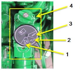
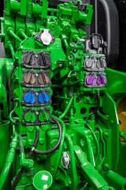
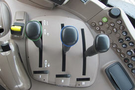
Mechanical control valves
Overview
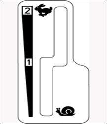
The tractor may be equipped with one type of mechanical control valves: premium (450 Series).
Premium-couplers control valves also have an additional lock function (position 3), which holds the control lever in the raise or lower position until the pressure in the oil circuit has reached a predetermined value (e.g., when the control cylinder has reached its end position).
In position 2, the control lever returns to neutral as soon as it is released and is the setting for normal hydraulic operation.
If an implement is connected, pressure connection has to be connected to the lower coupler. With standard SCVs, a valve prevents sudden loss of pressure caused by leakage when the engine is shut off.
On premium SCVs, the likelihood of leakage is further diminished.
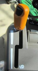
Premium mechanical control valve (premium)
Position 1
Position 2
Position 3
Hydraulic oil flow control
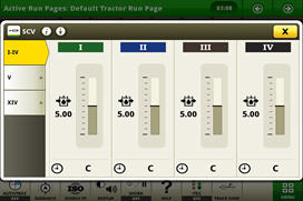
Electrical control valves
Overview
The tractor may be equipped with the premium (450 Series) control valves. All main characteristics can be controlled by the CommandCenter™ display.
CommandCenter hydraulics option
Example options of rear valve configuration
3351 – five electronic SCVs (five SCV premium)
3361 – six electronic SCVs (six SCV premium)
Hydraulic control options
E-SCV controls on the right-hand console
M-SCV controls on the right-hand console
E- SCV controls on CommandARM™ controls
E-SCV controls on optional joystick (reconfigurable)
Hydraulic set up
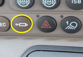
Shortcut button right-hand console
Overview
Simply push the hydraulic symbol on the right-hand side console or the CommandCenter and the CommandCenter display shows a setup menu to:
Monitor valve status - detent, float, or neutral
Adjust maximum flow and detent (combine for both direction or separate extent and retract adjustment)
Hydraulic shortcut button on right-hand console
Hydraulic shortcut button CommandCenter
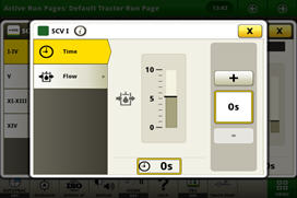
Detent setup
Overview
Time detent - this is particularly useful when repeat SCV operations are performed, such as lowering a mower-conditioner plow or cycling planter markers.
Continuous flow detent - this is particularly useful when a hydraulic motor is used, such as on an air seeder.
Detent setup
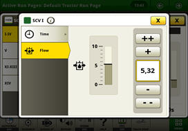
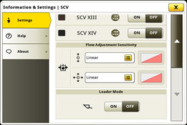
SCV flow setup
Overview
SCV flow rate can be programmed between 0.04 and 10 allowing fine tuning for implements with different hydraulic requirement.
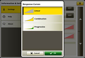
Behavior can be set between linear (red), progressive (green), or a combination (yellow) for exact flow modulation and precise valve management.
Linear means that the distance travelled by the SCV/ICV corresponds to the distance travelled by the control lever/multifunction lever
Progressive means that initially the distance travelled by the SCV/ICV is less than that travelled by the control lever/multifunction lever (giving a more sensitive start to the movement)
Flow setup
Three flow options
Flow characteristic setup
Combination is an intermediate stage between the two settings listed above.
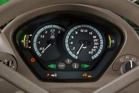
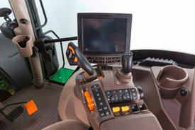
ComfortView cabs feature a modern, automotive-style instrument panel as base equipment. The instrument pod has two large analog dials for engine and tractor speed, as well as two smaller dials that display fuel level, diesel exhaust fluid (DEF) level, and coolant temperature. The steering column and dash are adjustable to suit the operator's needs. The column tilts toward the operator and a lever on the left-hand side allows for the column to telescope out to the desired level.
A dimming mode automatically reduces the brightness of the instrument illumination when the tractor lights are used.
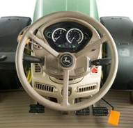
Steering column control panel
Cab and controls of 6R Tractor
Steering column on 6R Tractor
Instrumentation control panel
Overview
The instrumentation panel has a row of information and warning lights across the bottom to monitor all important tractor functions. A three-stage warning system first gives information, then gives warnings, and finally, gives a stop alarm to prevent damage from occurring in the event of a component malfunction. An integrated power take-off (PTO) over-speed warning is incorporated into the diagnostics to ensure proper operation.
Instrumentation control panel
Dash instrument panel controls include:
Left side
Right side
Left-hand reverser
Two-speed and optional intermittent wiper
High-/low-beam switch
Key start/stop
Hazard switch
Road/work lights on/off
Self-cancelling turn signals/horn
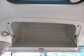
In-cab storage
Overhead storage compartment
CommandARM™ console storage compartment
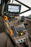
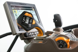
CommandARM controls
Overview
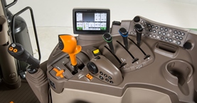
The 6R Series features a redesigned CommandARM console with all key vehicle functions in one place. The updated CommandARM layout is only available with Infinitely Variable Transmission (IVT™) and DirectDrive transmissions. The base 21.3-cm (8.4-in.) 4200 CommandCenter™ Display or optional 25.4-cm (10-in.) (4600 CommandCenter Display is fully integrated onto the CommandARM and offers fast adjustment of additional tractor functions.
The CommandARM design allows for 37.5 degrees of total seat swivel and adjustable positioning matching the operator’s preference. (30 degrees right and 7.5 degrees left).
Hydraulic and hitch controls utilize fingertip paddle pots for raise/lower and extend/retract functions. The CommandARM offers up to a maximum of six electronic selective control valves (E-SCVs) (without electronic joystick). The optional electrical joystick replaces fingertip paddle pots for control of selective control vales (SCVs) and allows for programmable hydraulic functionality according to operator preference. A maximum of five E-SCVs can be ordered with the electronic joystick. For tractors with an IVT transmission, the CommandPRO™ joystick is available. Its 11 reconfigurable buttons enable the operator to have all necessary controls accessible without hand movements (for details, click here).
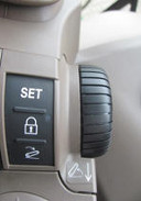
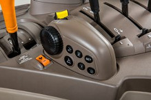
Controls for radio, lights, rotary beacon, and hazard flashers are located to the center right on the CommandARM along with PTO for front (if equipped) and rear PTO. Additionally, located on the right side of the CommandARM is an encoder wheel which allows for finite positioning of the rear 3-point hitch. There are three buttons near the encoder for set lock and return to height. Adjustment knobs for the 3-point hitch are located under the cover for the CommandARM storage compartment and allow for adjustment of the rate of drop, hitch height limit, and depth control.
The transmission control and throttle are placed on the left side of the CommandARM closest to the operator for convenient setting and adjustment. The throttle design incorporates buttons which control engine cruise speed, pedal lock/cruise control, and transmission Eco settings (for more information, refer to the AutoPowr™ or DirectDrive transmissions pages).
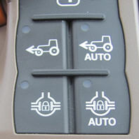
Located just to the right of the throttle is the auto-steer activation button and four sequence controls for iTEC™ functions. Behind the iTEC sequence controls are buttons which control the activation and deactivation of mechanical front-wheel drive (MFWD) and differential lock.
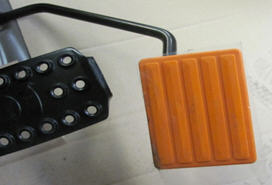
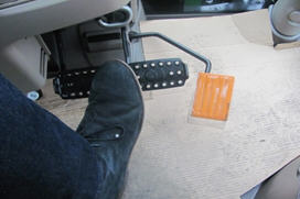
Differential lock can also be activated by foot switch on the cab floor. A feature in the 6R Series Tractor is auto steering angle dependent differential lock button.
Operators can easily identify controls by icons located near levers, and each functional area is color coded.
Functions:
Motion (throttle, transmission) - orange
MFWD and hydraulics (hitch and SCVs) - black
PTO - yellow
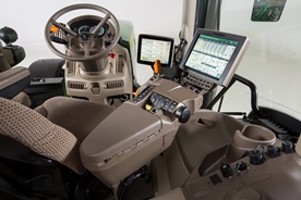
ComfortView cab with CommandARM console
Close up of controls on the CommandARM
Optional integrated crossgate joystick
CommandPRO controls (IVT only)
Hand throttle feature
3-point hitch control layout
Integrated differential lock features
Benefits
All main tractor functions in one place
Hand throttle module with integrated cruise control/pedal lock and Eco function
Integrated reconfigurable joystick
All controls and display move with the operator's movement or motion
Availability of optional 25.4-cm (10-in.) 4600 CommandCenter Display
Integrated storage compartment with hitch controls
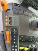
Right-hand console controls
Overview
The right-hand control console is angled for operator comfort and ease of operation. The design of the right-hand console is controlled by the type of SCVs chosen.
Mechanically actuated valves are controlled by traditional levers, while electronically actuated valves are controlled by fingertip paddle pots. Controls for the ComfortView cab are grouped by function on the right-hand console.
The modular console panel provides individual access to hand throttle, transmission controls, MFWD switch (if equipped), hitch command console, load/draft control, SCV, and PTO controls.
The console is also the location of the CommandCenter display. The CommandCenter allows the operator to customize important tractor functions.
This option requires a PowrQuad™ or AutoQuad™ transmission.
ComfortView cab right-hand console (AutoQuad transmission is shown)
Hitch control module on right-hand console
M-SCV controls on the right-hand console
E-SCV controls on the right-hand console
Benefits
Ergonomic placement of controls to match arm movements
Integrated hitch control module with draft wheel
Cab packages
Overview
The 6R Tractors have seven cab packages designed to match producers' operations. There are three levels of comfort - economy, standard, and premium. There are two control configurations available: a right-hand console for the PowrQuad PLUS or AutoQuad PLUS transmissions and the CommandARM console for the IVT and DirectDrive transmissions. There is an option for hydraulic cab suspension for the premium package. Below is a chart showing the available packages and what is included in each package.
Benefits
Easy ordering of cab features
Built-in comfort and convenience
Details
Base features in all cab packages:
Power outlet
Seven-pin signal interface socket
Multi-power outlet strip
Inner rear-view mirror
Cup holder on rear right-hand cornerpost
Front wiper and washer
Overhead compartment with one slot
Overhead storage compartment on left-hand side
Courtesy light, coat hook, floor mat
External starting connectors (outside under right-hand door)
iTEC control (code 8216)
Cab packages for 6230R and 6250R
Cab packages
Standard CommandARM
Premium CommandARM
Premium CommandARM and cab suspension
Standard cab with CommandPRO
Premium cab with CommandPRO
Premium cab with CommandPRO and cab suspension
Package code
2060
2064
2068
2089
2091
2092
Two panorama doors (left-hand and right-hand sides)
X
X
X
X
X
X
Standard seat (Grammer)
X
---
---
X
---
---
Premium seat (Grammer DDS)
---
X
X
---
X
X
Instructional seat
X
X
X
X
X
X
Bottle holder
X
X
X
X
X
X
Mirrors - right hand and left hand - manually adjustable and telescopic
X
---
---
X
---
---
Wide-angle mirrors - right hand and left hand - electrically adjustable
---
X
X
---
X
X
Front sun visor
X
---
---
X
X
X
Front and rear roller blind
---
X
X
---
---
---
Rear wiper and washer
X
X
X
X
X
X
Manual temperature controls
X
---
---
X
X
X
Automatic temperature controls
---
X
X
---
X
X
Hydraulic cab suspension
---
---
X
---
---
X
CommandPRO
---
---
---
X
X
X
Leather comfort package
---
X
X
---
X
X
Grammer is a trademark of Grammer AG Aktiengesellschaft.
Cab packages for 6110R, 6120R, 6130R, 6145R, 6155R, 6175R, 6195R, and 6215R
Cab packages
Economy right-hand console
Standard right-hand console
Standard CommandARM
Premium right-hand console
Premium CommandARM
Premium right-hand console and cab suspension
Premium CommandARM and cab suspension
Standard cab with CommandPRO
Premium cab with CommandPRO
Premium cab with CommandPRO and cab suspension
Package code
2050
2057
2060
2063
2064
2067
2068
2089
2091
2092
Two panorama doors (left-hand and right-hand sides)
X
X
X
X
X
X
X
X
X
X
Standard seat (Grammer®)
X
X
X
X
---
---
---
X
---
---
Premium seat (Grammer DDS)
---
---
---
---
X
X
X
---
X
X
Instructional seat
X
X
X
X
X
X
X
X
X
X
Bottle holder
X
X
X
X
X
X
X
X
X
X
Mirrors - right hand and left hand - manually adjustable and telescopic
X
X
X
---
---
---
---
X
---
---
Wide-angle mirrors - right hand and left hand - electrically adjustable
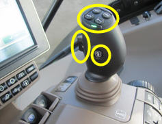
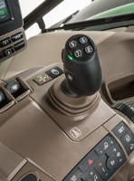
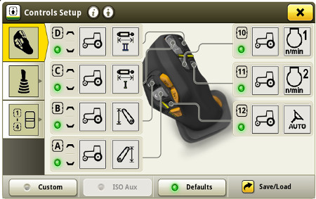
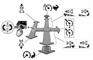
The optional CommandPRO joystick combines a unique driving strategy with reconfigurable controls.
CommandARM™ controls with CommandPRO
Layout and functions
1 – travel set speed buttons 1 and 2 2 – acceleration response button 3 – travel speed adjustment wheel 4 – reconfigurable buttons and rocker switches (button 12, rocker switches A and B)
4 – reconfigurable buttons and rocker switches (buttons 10 and 11, rocker switches C and D) 5 – activation button
Benefits
11 reconfigurable controls for both tractor and implement functions
Possibility to operate tractor and ISOBUS functions at the same time on the CommandPRO joystick
Intuitive and easy driving concept
Code
Description
2089
Standard Cab with CommandPRO
2091
Premium Cab with CommandPRO
2092
Premium Cab with CommandPRO and cab suspension
Default assignments
Rocker D: selective control valve (SCV) II (if equipped)
Button 10: engine set speed 1
Rocker C: SCV I (if equipped)
Button 11: engine set speed 2
Rocker B: front hitch (if equipped)
Button 12: AutoTrac™ resume (if equipped)
Rocker A: rear hitch (if equipped)
NOTE: For information about reconfigurability, please see operator's station functional area.
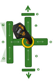
Driving strategy
The unique driving strategy is designed to deliver highest performance in combination with operator comfort making the daily work much easier and efficient.
Pedal and joystick mode are active at the same time
ActiveZero keeps the output speed actively at 0 km/h (0 mph) until command for acceleration is given independent of load or engine speed
Command top and zero speed simply by one push or pull
Unique inching control
Three easily adjustable travel set speeds
Two engine set speeds
Three acceleration response settings
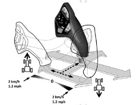
Inching control
The inching control of the CommandPRO joystick simplifies the attachment of implements. Once the joystick is pushed into the inching range, the tractor moves very slowly in the selected direction. Speed is dependent on the joystick position and can be speed between 0 and 2 km/h (0 and 1.2 mph). Maximum speed of the inching range can be set to 5 km/h (3.1 mph) with the travel speed adjustment wheel.
Unlike the main range, releasing the joystick means the speed is reduced until the vehicle stops completely. This allows the operator to fully focus on the implement and quickly stop if required.
Driving strategy
Forward movement
Reverse movement
1
Accelerate
Decelerate
2
Top set speed
Zero speed
3
Decelerate
Accelerate
4
Zero speed
Accelerate
5
Activate set speed
6
Select direction
7
Inching speed
8
Inching speed
CommandPRO joystick driving functions
Pedal and joystick mode active at the same time
The change between using the foot pedal or the joystick can happen while driving for ease of use and comfort. The simple rule is: the higher speed command is superior. When changing from the pedal to the joystick, there is a short overlap where the joystick takes over the command from the pedal before the pedal is released. Similar, when changing from joystick control to the foot pedal, the driver needs to push the foot pedal to the point of speed where the joystick is before it can take over.
Inching control on CommandPRO joystick
Three settings for acceleration and deceleration
The settings influence the following:
Characteristics of increase and decrease in speed for both CommandPRO joystick and foot pedal
Speed change value when flicking the CommandPRO lever forward or backward (triggering).
0.2 km/h (0.12 mph) in slow acceleration mode
0.5 km/h (0.31 mph) in normal acceleration mode
1 km/h (0.62 mph) in rapid acceleration mode
Acceleration characteristics when activating a travel set speed
Tractor behavior when commanding a change in direction of travel
To ensure comfortable and reliable deceleration of the tractor with both the foot pedal and the CommandPRO joystick the tractor is equipped with unique technology. The engine overspeed protection ensures that both transmission and engine are not overloaded when decelerating. Additionally, the anti-jackknife technology compares wheel speed of front and rear wheels when decelerating through the joystick, as this means that the front brakes are not applied but only through the rear axle. If the front wheels are moving quicker, the transmission automatically adjusts to ensure the same wheel speed and avoid the jackknife situation.
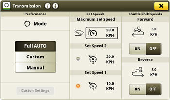
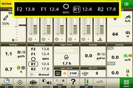
Travel set speeds
The travel set speed buttons on the CommandPRO joystick allow the operator to set two set speeds. The operator has to preselect the desired set speed by pushing the travel set speed button 1 or 2 and once the joystick is pushed to the right, the set speed is activated and the travel speed will be adjusted until the set speed is achieved. Additionally, the operator can set a maximum travel speed through the travel speed adjustment wheel or in the CommandCenter™ display.
There are different ways to set or adjust the set speeds:
In the CommandCenter display
If current travel speed should be saved as a set speed, press and hold either one of the buttons for 2 seconds and the speed is saved
When already using a set speed, it can be adjusted with the travel speed adjustment wheel
The operator can also set a dedicated set speed when changing the travel direction. For example, the tractor is driving forward at 10 km/h (6.2 mph) and for reversing the reverse shuttle shift speed is set to 5 km/h (3.1 mph). This means when the shuttle shift takes place, the tractor will accelerate to 5 km/h (3.1 mph) in reverse direction. This function can be turned on/off and set to the dedicated speed in the CommandCenter display.
Set speeds and shuttle shift speeds in the CommandCenter
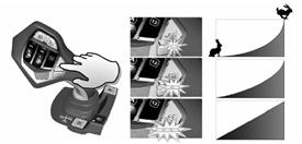
Acceleration response
The three settings for acceleration and deceleration with the CommandPRO joystick can be changed by pressing acceleration response button. Three light-emitting diodes (LEDs) next to the set button indicate the currently activated setting.
Smooth acceleration and deceleration – one LED glows
Normal acceleration or deceleration – two LEDs glow
Rapid acceleration and deceleration – three LEDs glow
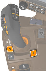
CommandPRO joystick with neutral and park position
Park lock and neutral
The park lock is disengaged automatically when commanding any direction of travel. Additionally, it engages automatically when the driver leaves the driver seat while the tractor is stationary. If the tractor is equipped with a trailer brake, this logic also applies for the trailer brake.
The buttons for the park lock and neutral position are next to the CommandPRO joystick on the CommandARM controls. There is no park lock or neutral position available in the left-hand reverser.
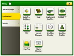
The Generation 4 CommandCenter creates the primary user interface for 6R Tractors. The Generation 4 CommandCenter provides an excellent, user-savvy operating experience.
Producers can also use a variety of implements with the Generation 4 CommandCenter as it is ISOBUS virtual terminal (VT) capable.
Expect machine productivity gains, along with increased operator confidence, thanks to a simple, customizable interface. The reliability of the Generation 4 CommandCenter also aids in optimal operating experience and maximizes uptime.
4200 Section Control and Data Sync activation plus CommandCenter AutoTrac activation
1857
4600 CommandCenter Premium Activation 3.0
1861
4600 CommandCenter Automation Activation 1.0
186S
4600 CommandCenter Automation Activation 3.0
NOTE: CommandCenter AutoTrac activation stays with the tractor. NOTE: 6155RH only available with code 1867.
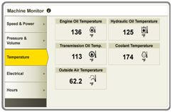
Machine monitor
Machine monitor page
The machine monitor application provides the user instantaneous readings about the status or condition of the machine. Values shown in the machine monitor vary by application, but typically include parameters like engine speed, coolant temperature, and ground speed. The machine monitor supports run page modules in the layout manager, allowing the user to populate specific machine parameters directly to a run page.
NOTE: The machine monitor application replaces part of the Universal Performance Monitor in previous machines.
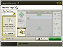
Layout Manager
Layout Manager selection page
Layout Manager module build
The Generation 4 CommandCenter features a modular-designed layout manager so an operator can easily create the structure that meets the operator’s demands. From the factory, machines are equipped with standard run pages. An unlimited amount of run pages can be added to the Generation 4 CommandCenter based on operator preference or operational needs. Toggling between run pages is as easy as swiping the screen or using the arrow buttons on the top right portion of the title bar.
Users and access
Users and access allow the owner to lock out certain functions to prevent operators from accessing or changing settings. Lock-out functions are managed with an owner-defined four-digit code.
Lockout features are available for:
Precision Ag Technology applications
Hitch
Hydraulic
Transmission
Power take-off (PTO)
FieldCruise™ engine controls
Display
Machine monitor
On-screen help and diagnostic text
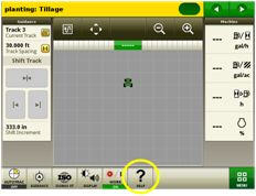
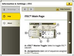
There are a few different ways to get meaningful on-screen help when navigating the Generation 4 CommandCenter. Operators can find the help icon on the shortcut bar on the bottom of every page. This icon gives detailed information on everything from tractor operation to application information. Simply select the help icon and navigate to the information section that is needed.
Help icon
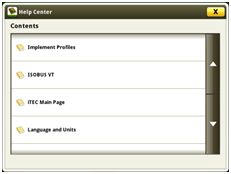
Help center main page
Additionally, application-based help is also available in all locations of the CommandCenter. Simply click on the (i) icon available on the title bar and it will lead directly to more information on the application currently being used.
Context-based help icon
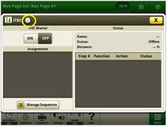
Context-based help iTEC™ main page
Diagnostic text and information are available for better understanding of whether applications are operating as directed.
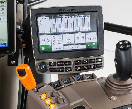
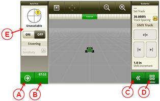
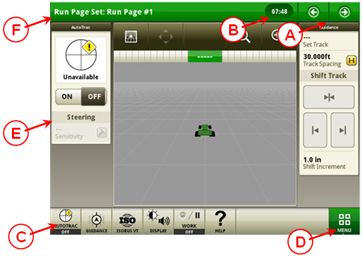
John Deere 4200 CommandCenter
A. Next run page B. Status center C. Expand shortcut keys D. Menu E. Run page
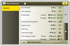
Work monitor
Work monitor page
The work monitor application displays the performance information about the task being performed by the machine. The user is shown averages, totals, and productivity of the machine, such as area worked, average working speed, and fuel usage. The values of the work monitor can be reset by the user at any time. Specific values of the work monitor can be configured by the user to be shown on a run page.
NOTE: The work monitor application replaces part of the universal performance monitor in previous machines.
Video capability
Tractors with a 4200 CommandCenter are equipped with one video input and tractors with a 4600 CommandCenter have two video inputs (one port to connect two cameras via a Y harness). The operator can set a variety of triggers, including reverse, PTO, hitch, and selective control valve (SCV) levers to activate the camera. The image will then appear on the CommandCenter display. The camera (video observation system) is available through John Deere Parts and Ag and Industrial (A & I) Products.
John Deere Generation 4 CommandCenter processors
A Generation 4 CommandCenter is made up of a processor and a display. Two processor options are available for the Generation 4 CommandCenter.
The 4600 Processor is the premium processor. Available features with the premium processor include:
Compatible with 25.4-cm (10-in.) touchscreen display
Two video camera inputs (one port to connect to two cameras via a Y harness)
One USB input
AutoTrac capable (machine-specific activation sold separately)
25.4-cm (10-in.) 4600 CommandCenter display
The 4200 Processor is base equipment on all 6R Tractors. It offers:
Compatible with 21.3-cm (8.4-in.) touchscreen display
One video camera input
One USB input
AutoTrac capable (machine-specific activation sold separately)
Tractors
4600 Processor
4200 Processor
6R
Option
Standard
Display options
Generation 4 CommandCenter displays are available in the following configurations:
21.3-cm (8.4-in.) display on the 4200 CommandCenter
25.4-cm (10-in.) display on the 4600 CommandCenter
For those wanting to maximize their viewing real estate, the 25.4-cm (10-in.) touchscreen color display is an excellent choice. With the 25.4-cm (10-in.) display, the title bar and all shortcut keys can always be viewed. Operators can monitor more items at once on the 25.4-cm (10-in.) touchscreen display.
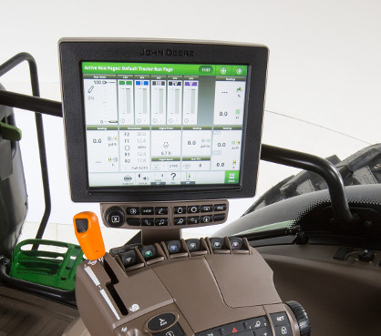
John Deere 4600 CommandCenter
A. Next and previous run page B. Status center C. Shortcut keys D. Menu E. Run page F. Title bar
The John Deere Infinitely Variable Transmission (AutoPowr/IVT) utilizes a combination of mechanical and hydrostatic power, providing stepless and continuous power across an infinitely variable range of speeds.
Single-speed lever is used for intuitive and accurate control of ground speeds as slow as 50 m/h (0.03 mph) to 40/50 km/h (25/31 mph). In model year 2015, the transmission was revised so transport speeds are reached at lower engine rpms, ultimately reducing fuel consumption and in cab noise. Software has also been revised to ensure under acceleration engine rpm is kept to a minimum within the engines peak torque band.
AutoPowr/IVT transmission
Benefits
Easy to operate
Four mechanical modes lead to excellent performance and reduced fuel consumption
Revised ratios bring transport speeds at reduced engine rpm – reduced fuel consumption and increased comfort
Precise management of forward speeds
Less shifting time means better management of the implement
Details
Requires 240-amp alternator (code 8743) (6110R, 6120R, and 6130R)
Requires code electrohydraulic (EH) selective control valves (SCVs) and 240-amp alternator
Requires braked front axle (code 6070)
Requires hydraulic trailer brakes (code 8756)
Requires B-speed rated tires and front fenders (8011 or 8012)
NOTE: Not available in 6155RH.
Code
Description
1558
AutoPowr/IVT – 50 km/h (31 mph)
Details
Requires code EH SCVs
Requires 240-amp alternator (code 8743) (6110R, 6120R, and 6130R)
NOTE: Not available in 6155RH.
Code
Description
1557
AutoPowr/IVT – 40 km/h (25 mph)
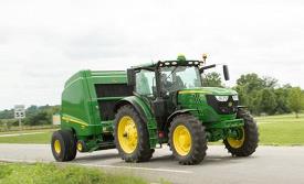
50 km/h (31 mph)
6R in transport
The following features are part of the 50 km/h (31 mph) package:
Triple-Link Suspension (TLS™) Plus system with brakes for improved braking capacity
Rim and tire matching with fixed tread rims to minimize vibration and increase ride comfort
Trailer brakes
Front and rear fenders
Set-speed adjusting wheel
Overview
The set-speed adjusting wheel is the rotational thumbwheel located on the speed control lever. The wheel is quick and easy to adjust with the operator’s thumb and rotates infinitely with no stop or start position. When the operator rotates the thumbwheel, the ground speed of the tractor is increased by 0.2 km/h (0.12 mph) when the tractor is traveling below 20 km/h (12 mph). When the tractor is traveling above 20 km/h (12 mph), the tractor is increased by (1) km/h (0.6 mph). The set speed adjuster is used to set the maximum commanded forward or reverse speed in each speed band.
As the operator moves the lever within or between speed bands, the electronic management system ensures smooth, quick, and powerful acceleration or deceleration, regardless of load or ground speed.
While in motion, the operator can adjust the maximum speed of each speed band. With the lever in band one, the target maximum speed can be adjusted to 20 km/h (12 mph). With the lever in band two, the maximum speed of 40/50 km/h (25/31 mph) can be defined depending on transmission option. When stationary, all set speeds, both forward and reverse, may be adjusted while the left-hand reverser is in the power zero position.
Left-hand reverser if equipped with CommandPRO
Benefits
Tractors without CommandPRO allow for temporary stationary control of the tractor without using the brakes. For tractors with CommandPRO, ActiveZero is always in place when the tractor is not in N or P and brakes are not applied.
Quick and easy way for the operator to change the direction of the tractor.
Ensures that the tractor cannot be operated with the park lock on.
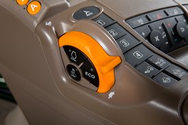
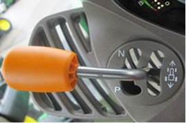
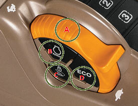
Electronic hand and foot throttle
Overview
The tractor ground speed is controlled via the accelerator and hand throttle. The engine rpm can be set to a specific ground speed using the hand throttle (A). The following functions are available for tractors without CommandPRO:
Button (B) activates and de-activities the FieldCruise™ system (with two available pre-sets), which is an engine rpm limiter.
The specific ground speed set can be set by pressing button (C); this pedal lock feature works like the cruise control on a car (only functions when foot throttle is ordered).
Button (D) allows the operator to drive with the minimum target rpm with ECO on.
NOTE: Button (D) is only active in custom mode.
Thumbwheel located on the speed control lever
Lever slot between speed brands
Drop-down information for set speeds on CommandCenter™ display when rotating the thumbwheel
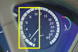
Set speed indicated in the dashboard
Benefits
Quick and precise speed changes
Fine-tuning via the speed wheel
Two steps in the slot of the speed control lever to program two set speeds
Speed feedback on the analog dashboard – the needle shows the actual speed, and red lights around the needle show the commanded speed
Easy-to-handle exact-speed settings through the CommandCenter display and the speed wheel
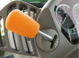
Left-hand reverser
Overview
An easy-to-use left-hand reverser is available in all the AutoPowr/IVT transmissions. The reverser control is located at the 10 o’clock position on the steering column for intuitive control. For tractors without the CommandPRO™ joystick, the left-hand reverser incorporates the following controls:
Forward direction selector
Reverse direction selector
Park (P) - Park lock (P) - Tractor cannot move and the trailer brakes are engaged. Lever must be in the (P) park position to start the tractor.
Neutral (N) – Tractor is in a non-parked position and capable of movement.
Power zero – Tractor is held stationary by the transmission.
Left-hand reverser
For tractors with CommandPRO, the left-hand reverser incorporates only forward and reverse direction selection and the lever is self-centering. The park (P) and neutral (N) positions can be selected on the CommandPRO.
Full auto screenshot on CommandCenter display
Custom mode
Overview
Custom mode allows the operator to customize the AutoPowr/IVT transmission settings when full auto mode is not desirable. In custom mode, operators can turn ECO on and off. This can either be done by pushing the ECO button on the side of the hand throttle module or by selecting ECO in the transmission settings page of the CommandCenter display. When accelerating with ECO on, the tractor minimizes engine speeds, which reduce acceleration aggressiveness. As a result, ECO on should reduce fuel consumption in lighter, steady loads. In contrast, when accelerating with ECO off, engine speed can be higher aggressively to maximize productivity. The higher engine speeds with ECO off better enable the tractor to quickly recover from sudden load increases and not lose as much ground speed when load increases occur.
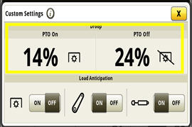
In custom mode, the engine droop settings can be defined between 4 percent and 30 percent with PTO on and off. The higher the droop percentage, the more the engine rpm will be reduced when pulling before a transmission ratio change is made.
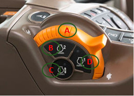
Hand throttle
The following functions are available for tractors with CommandPRO:
Button (B) and (D) activate and de-activate engine set speeds that can be set in the CommandCenter display.
Button (C) can be used to fix the engine speed command to the current hand throttle position (no automatic engine speed control).
Hand throttle when equipped with CommandPRO
Foot throttle
Benefits
Define setting of the engine speed and its limit with the FieldCruise system
Quick attainment of desired speed
Pedal lock function allows command foot throttle speed to be maintained
AutoPowr/IVT selector control via CommandCenter display
Overview
The AutoPowr/IVT application setting employs four modes to take full advantage of the engine-transmission communication: full AUTO, custom, pedal and manual.
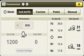
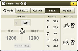
Full AUTO mode
Overview
Full AUTO mode enables the tractor to make adjustments to the transmission operating mode automatically, based on the engine and transmission speeds and the load on the tractor. This should be the AutoPowr/IVT transmission setting for 95 percent of all applications.
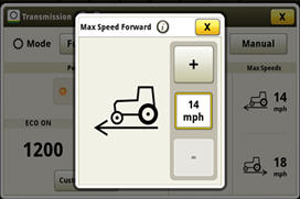
Full AUTO mode switches between load control and fuel economy mode seamlessly, with no involvement from the operator, as conditions and applications change. Fuel economy mode automatically switches off when the power take-off (PTO) is engaged to provide full PTO power. Operators can set the maximum forward and reverse speeds for the tractor in their particular application.
NOTE: Activation ECO is not available in full auto mode.
Operator presses brake pedal to stop the tractor
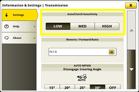
AutoClutch sensitivity change on CommandCenter display
Benefits
This feature makes the AutoPowr/IVT an ideal transmission for operations that require a lot of speeds (like baling or loader work).
Upon release of the AutoClutch, the tractor will accelerate to the previous command speed (ideal for round baling).
Excellent modulation makes inching to implements and attachments easy.
Torque
Overview
The AutoPowr/IVT transmission is a combination of mechanical and hydraulic components that can provide low speed with extremely high levels of torque:
Allows the tractor to smoothly pull away, even under high loads
Enhances front loader operation by delivering high torque, driving the tractor into the pile without slippage
Retains constant working speeds with PTO implements, which tend to push the tractor (spading or rotary cultivator)
Creeper mode
Creeper mode is a standard feature on the AutoPowr/IVT transmission. Down to 50 m/h (164 ft/h), the creeper mode is activated when the selected speed is below 2.1 km/h (1.3 mph) in set position 1.
When the tractor moves below 600 m/h (1968 ft/h), the engine speed is independent of travel speed. This allows the operator to choose the engine speed that best fits the task (rated speed for hydraulic or PTO usage, or low idle for fuel-saving operation). No additional power is needed.
Customizing speed of direction on CommandCenter display
Droop setting on CommandCenter screen
Benefits
Ensure that the operator has the best driving options when required
Independent droop settings allow the operator improved performance and flexibility
Pedal mode settings
Overview
Pedal mode allows the operator to change the tractor’s ground speed independently from the engine speed. The ground speed is controlled through use of the foot pedal while the hand throttle determines engine speed. Maximum ground speed is determined by the location of the speed control lever in the speed band. Operators can lock-in a desired ground speed without pressure on the foot pedal using the pedal lock button (as described above). To unlock the foot pedal, the operator can tap the foot pedal, press the lock button, or press the brake pedal. When releasing the foot pedal, the vehicle decelerates to a safe creep speed. To come to a complete stop, the brake pedal should be depressed.
Pedal mode display on CommandCenter display
Benefits
Pedal mode is ideal for applications like mowing, baling, or hedge cutting, where it is important to keep the engine speed at a constant rpm independent from the ground speed.
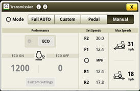
Manual mode settings
Overview
Manual mode makes the transmission and engine independent of each other. The transmission does not automatically adjust engine rpm to save fuel. This can prove to be useful in applications like loader work, where the variability of engine speed based on load is not needed.
Manual mode display on CommandCenter display
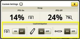
Load anticipation feature
Overview
The load anticipation feature allows the AutoPowr/IVT transmission to predict how much load the engine expects from the activation of the hitch or a particular SCV function.
In full AUTO mode, all load anticipation features are active. In custom mode, they can be turned on or off in the custom settings page. When an SCV or the hitch is activated, the engine speed is raised to 1500 rpm (as long as the commanded throttle position is over this value). This creates a boost in engine power which improves hydraulic performance and prepares the engine for potential load situations (for example, returning an implement to work). Also added is PTO load anticipation. If it is turned off, the engine does not react to PTO engagement and engine speed is controlled purely based on load. If turned on (in custom), when the PTO is engaged, the engine rpm will rise to throttle position or pre-defined PTO cruise setting.
Load anticipation display on CommandCenter display
Benefits
John Deere exclusive feature
Tractor recognizes when additional engine rpm is needed
Saves fuel, because the engine shuts down when no additional power is needed
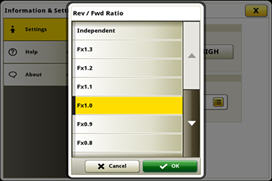
Forward/Reverse relationship
Overview
Similar to the AutoQuad™ PLUS transmission, the AutoPowr/IVT transmission can also adjust the forward/reverse speed ratio. The reverse speeds can be set to a maximum of 30 percent higher and 70 percent lower than forward speeds, but only in range 1. In range 2, the forward-to-reverse speed ratio is 1:1, up to 22 km/h (14 mph). Above that, the reverse speeds will only go up to 30 km/h (19 mph).
Section of forward/reverse relationship via CommandCenter display
Brake with integrated AutoClutch function
Overview
With the AutoPowr/IVT transmission, no clutching is required to stop the tractor. After the brakes are released, the tractor automatically accelerates back to its previous speed (if using hand throttle). The effect of AutoClutch can also be set via the CommandCenter display.
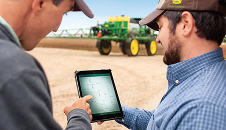
When you buy John Deere equipment, you expect reliability. You also know that problems can happen, and a product is only as good as the support behind it. That’s why John Deere equipment is prepared with technology that senses potential issues and can alert you and your dealer promptly—in the cab or anywhere you are.
John Deere Connected Support is a revolutionary change to support that leverages technology and the connectivity of JDLink™ telematics to prevent downtime and resolve problems faster. These tools decrease downtime by an average of 20 percent, enabling faster responses to unexpected problems and reducing technician trips to your machine. For some issues, unplanned downtime can even be prevented altogether through prediction of the issue.
With your permission, John Deere Connected Support:
Keeps you running by monitoring machine health and promptly alerting you and your dealer of issues
Saves time by remotely viewing in-cab displays, reducing trips to the machine
Reduces or even eliminates technician trips to a machine through remote diagnostic and remote software reprogramming capabilities
Connects experts with the information needed to respond to downtime faster and prevent it altogether
With more than a decade of experience leveraging connectivity to solve problems, no one else has the experience, tools, and knowledge to keep you running as John Deere and your John Deere dealer can. Connected Support is an in-base feature on all John Deere products with factory- or field-installed JDLink.
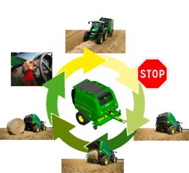
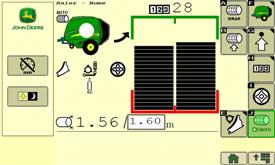
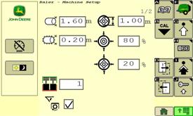
The optional Tractor-Baler Automation (TBA) makes baling easy. This exclusive system manages most of the baling process and gives the producer the following advantages:
High baling comfort a single action to bale instead of four.
Error proof baling - even after 10 working hours, the system does not forget any action; a true advantage for an inexperienced driver.
Constant bale quality - same diameter bale after bale
Constant productivity - no reduced efficiency due to operator fatigue.
When used with a John Deere ISOBUS tractor, electric selective control valve (E-SCV), and (IVT™) transmission, the system will be able to:
Stop the tractor when bale size is reached
Wrap the bale
Open the gate
Close the gate when bale is unloaded
The only action remaining is to forward reverser and manage the steering.
If the John Deere tractor is not equipped with IVT but has E-SCV and ISOBUS, opening and closing can be automated.
A single touch on SCV, brakes, or reverser will disengage the automation. In the same way, automated open/close can be momentarily stopped when unloading in hilly conditions.
Tractor-Implement Automation is an exclusive green on green advantage. This advanced technology option has won awards at SIMA and Agritechnica farm equipment show in Europe, a true cost/value guarantee.
NOTE: to run through fully automated mode, a John Deere ISOBUS tractor with E-SCV and IVT is required. A baler activation key and a tractor activation key (different) have to be ordered.
ISOBUS certified balers
Plug in and bale with ISOBUS
ISOBUS certified = compatibility guarantee
The 990 and 960 Balers offer ISOBUS compatibility as base equipment. This standardized communication not only allows the use of John Deere GreenStar™ 2 1800, 2600, or GreenStar 3 2630 Displays, but also the use of other ISOBUS conform competitive monitors.
Adapter harnesses for non-ISOBUS tractors are available.
User friendly interface
Main page with simple and clear pictograms
Bale or soft-core density adjustments
The Baler interface displays information that is needed. The 900 Series monitors provide all required information:
Bale shape and diameter
Drop floor and knives position
Variable core activation
Tying process status
Gate position
Maintenance status
Adjustments can also be managed from the operator's station:
Bale size and density
Variable core diameter and density
Net and twine tying parameters
Knife selection
Automated lubrication
Tractor-Baler Automation status
Bale counter resets
GreenStar 2 1800 has the ideal display for baling application
GreenStar 2 1800 Display ordered with the baler
The 900 Series Balers can be teamed with all ISOBUS certified displays. The GreenStar 2 1800 monitor can be ordered with the baler to match traditional baling requirements. When not baling this display can be used for other functions such as guidance and spraying applications when connected to an appropriate receiver and implement.
All ISOBUS displays will fit the 900 Series
GreenStar 3 2630 fits the most demanding user needs
The 960 and 990 Balers can be ordered without a monitor for producers who already have an ISOBUS display, or for those who search more advanced application (field management). Displays other than John Deere GreenStar 2 1800 can be purchased through Ag Management Solutions (AMS) pages.
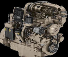
John Deere 6R Series Tractors feature the reliable and proven PowerTech PVS 6.8L and PSS 4.5L and 6.8L engines. These air-to-air aspirated engines deliver a power bulge above rated power to provide excellent torque in demanding applications.
Key features:
Series turbochargers (PSS only)
Variable geometry turbocharger (VGT)
Air-to-air after cooling
High-pressure common rail (HPCR) fuel system
Engine control unit (ECU)
PowerTech PSS/PVS engine identification
After treatment
S – Exhaust filter and selective catalytic reduction (SCR)
X – Exhaust filter
Turbocharger
V – VGT
S – Series turbochargers
W – Wastegate turbocharger
Technology
P – PowerTech Plus
E – PowerTech E
PowerTech PSS 6.8L engine
Benefits
A constant power range of 2100 rpm down to 1500 rpm
Power bulge of 10 percent
Greater tractor productivity
Responsive power reducing the need to downshift the transmission
Details
To match the engine power characteristics and improve the operation economy of the machine, the rated engine speed is 2100 rpm.
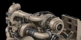
Series turbochargers
Overview
The PowerTech PSS 4.5L and 6.8L utilizes two turbochargers – a VGT and a fixed geometry turbocharger, providing the torque rise and engine response needed to meet varying load conditions.
Fresh air is first drawn into the low-pressure fixed geometry turbocharger and compressed to a higher pressure. The compressed, higher pressure air is then drawn into the high-pressure VGT, where the air is further compressed. By splitting the work between two turbochargers, both can operate at peak efficiency and at slower rotating speeds.
PowerTech PSS engine series turbochargers
Benefits
Deliver high power density
More low-speed torque and responsiveness to meet varying load conditions
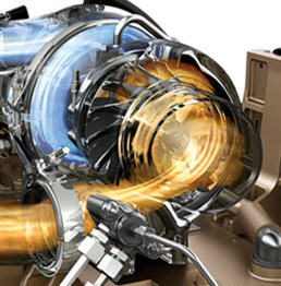
VGT
Overview
The VGT is electronically controlled and actuates the turbo vanes as required to maintain peak engine performance.
The turbocharger’s vanes are in the exhaust flow. The opening or closing of the vanes changes the outlet volume and airflow speed against the turbocharger turbine. When exhaust flow is low, the vanes are partially closed. This partial closure increases the pressure against the turbine blades to make the turbocharger spin faster and generate more boost pressure.
The ability to keep the airflow at optimum levels provides more consistent engine boost pressure and the ability to respond to load quickly across the entire engine rpm range. This system is without the turbo lag that can be found on some engines.
PowerTech VGT
Benefits
Increased low rpm torque
Quicker response to load
Increased peak torque
Improved fluid economy
Improved performance at high altitudes
Air-to-air after cooling
Overview
Air-to-air after cooling lowers the intake manifold air temperature and provides more efficient cooling while reducing cylinder firing pressure and temperatures for greater engine reliability. Since lower temperature air is denser, a higher volume of air flows into cylinders so the engine can meet the increasing horsepower demands. Lowering the intake manifold and cylinder temperatures also aid in lowering the combustion temperature, which lowers the NOx produced as a result.
Benefits
Higher horsepower
Less NOx production
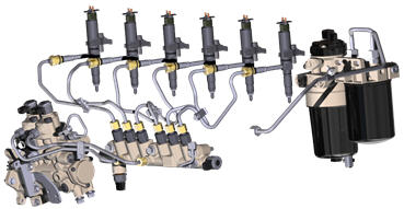
HPCR fuel injection system
Overview
Every PowerTech PSS 4.5L and 6.8L engine utilizes a HPCR fuel system to efficiently supply fuel to injectors. The high-pressure fuel pump instantly responds to requirements for more or less fuel flow or pressure. This electronically controlled, high-pressure pump delivers pressure on demand according to the application requirements. Pressure on demand ensures an efficient injection system resulting in high-injection pressure independent of engine speed.
High-pressure common rail
Benefits
Instantly respond to load changes reducing the need to change gears
Improved fluid economy
Engine control unit (ECU)
Overview
The ECU uses signal inputs from sensors and pre-programmed performance modeling to control critical engine functions such as fuel quantity, injection timing, air-to-fuel ratio, multiple fuel injections, amount of cooled exhaust gas recirculation (EGR), and a host of other control parameters.
ECU
Benefits
Optimized fluid economy
Maximum engine performance
Details
Each injector is controlled individually by the ECU. The ECU turns the injector on and off during each firing cycle to control the fuel delivery into each cylinder.
Load and speed sensing allow each cylinder’s fuel delivery rate to be adjusted independently at the individual injector. With each injection cycle, the ECU can make the following adjustments on the go:
Number of injections
Fuel pressure in the common rail
Start of injection
Duration of injection
This management system is connected to the transmission, allowing the engine and transmission to respond simultaneously.
Cold weather and high-altitude compensation are also precisely controlled for quality starts regardless of weather and maximum performance at high elevations. The ECU also features improved diagnostic capabilities. It is faster, has more working memory, and is responsible for monitoring and executing all aspects of the Integrated Emission Control System.
CommandCenter™ console TLS Plus provides exclusive front suspension using a hydropneumatic self-leveling system to increase productivity and improve ride dramatically. TLS Plus provides more control over the front suspension of the tractor. In the field, the TLS Plus front suspension maintains ground-to-tire contact, enabling more power to the ground.
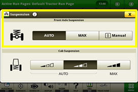
Front axle adjustment on CommandCenter
Auto mode
The TLS Plus reacts to inputs, which provides the best comfort and stability. Inputs include travel speed, implement weight, draft characteristics, and braking activity. The TLS Plus activates whenever the tractor exceeds 1.5 km/h (0.9 mph).
Maximum mode
The suspension is set to maximum hardness, which is preferable for front loader operation. This allows the operator to adjust the suspension for different situations. If the tractor exceeds 35 km/h (22 mph), the hardness is reduced to provide greater driving comfort. When dropping below 25 km/h (15 mph), maximum is reactivated.
Manual mode
This setting can be useful when attaching mounted implements to the front hitch. When activated, the axle settles in its mid position and then can be raised or lowered manually with the touchscreen or shortcut buttons F and G. The manual setting is overridden when the travel speed exceeds 5 km/h (3 mph) and returns to the previously selected setting of automatic or maximum.
The system
Vertical linkage double-acting cylinders
First link: vertical linkage
Two double-acting hydraulic cylinders control the vertical movement of the axle, which leads to excellent sensitivity.
Exclusive long-longitudinal member
Second link: longitudinal linkage
This linkage controls longitudinal movement of the axle. It is the connection point for pulling and braking forces generated by the front axle to the tractor’s center of gravity. This increases the tractor’s stability and the tractor’s draft and drawbar performance.
Third link controlling lateral movement
Third link: lateral linkage
This third link holds the axle laterally. These few simple components ensure excellent suspension quality and reliability with reduced maintenance.
A full stroke of the suspension typically takes 1 second, allowing the system time to distinguish between typical terrain inputs or level changes. This prevents overreactions.
In addition to active central leveling of the suspension, the John Deere TLS Plus adopts a constantly variable rod side pressure by using a closed loop system. When the suspension reacts at a different frequency, which could be detrimental to driver comfort, the system then fine-tunes the rod side pressure, changing the spring stiffness and improving the ride behavior.
*Not available in 6155RH
Capacities
Transmission-hydraulic system
PowrQuad™/AutoQuad™: 71 L 18.8 U.S. gal. DirectDrive™ ECO: 75 L 19.8 U.S. gal. IVT: 81 L 21.4 U.S. gal.
Crankcase oil volume
23.5 L 6.2 U.S. gal.
Fuel tank
330 L 87.1 U.S. gal.
Diesel exhaust fluid (DEF) tank
20 L 5.3 U.S. gal.
Cooling system
28.2 L 7.4 U.S. gal.
Dimensions
Front axle center
MFWD/TLS™ axle under differential housing w/ 420/90R30 tires: 537 mm 21.14 in.
Wheelbase
2800 mm 110.2 in.
Drawbar
Drawbar category
Category 3
Maximum vertical load
Category 3: 1600-2800 kg 3525-6170 lb Maximum vertical load dependent on drawbar position
Electrical system
Type of bulb in headlight (Halogen, Zenon, LED)
Type of bulb in beacon (Halogen, Zenon, LED)
Total cold cranking amps
1230 CCA With cold weather pakcage or IVT: 1400 CCA
Battery options
12 V
Alternator size
Standard: 200 amp Optional: 240 amp
Engine performance
Rated PTO power (hp SAE)
104 kW 140 hp
Engine peak torque
At 1,600 rpm: 817 Nm 603 lb-ft
Rated power
97/68EC: 129 kW 175 hp
Engine specifications
After treatment type
DOC/DPF/SCR
Aspiration
Turbocharged, variable geometry turbocharger with air-to-air aftercooling and cooled exhaust gas recirculation
Engine type
Diesel, in-line, 6-cylinder, wet-sleeve cylinder liners with 4 valves-in-head
Engine family
HJDXL06.8309
Emission level
Final Tier 4
Description
John Deere PowerTech™ PVS
Displacement
6.8 L 415 cu in.
Rated speed
2100 rpm
Front axle
Front axle differential lock
MFWD: limited slip Triple link suspension (TLS™): limited slip Triple link suspension (TLS™) with brakes: full-locking electrohydraulic
Type
Standard: MFWD Optional: Triple link suspension (TLS™)
Hydraulic system
Number of rear selective control valves (SCVs)
Standard: ISO Couplers: 3 Optional: ISO Couplers: 3-6
SCV control
Mechanical
Available flow at a single rear SCV
100 L/min 26.4 gpm
Type
Closed-center, pressure/flow compensated
Pump rated output
Standard: 60 cc pump: 155 L/min 41 gpm
Key Specs
Hydraulic pump rated output
Standard: 60 cc pump: 155 L/min 41 gpm
Rated engine power
97/68EC: 129 kW 175 hp
Engine description
John Deere PowerTech™ PVS
Rear hitch category (SAE designation)
Standard: Category 3/3N: 4300 kg 9480 lb Optional: Category 3/3N: 4850 kg 10690 lb
Fill out this form to request a quote. A representative will get in touch with you as soon as possible.
Thank you for submitting.
Request Service
Fill out our request form to contact us about service.
Thank you for submitting.
Request Parts
Fill out our request form to contact us about parts.
Thank you for submitting.
Request Used Parts
Fill out our request form to contact us about used parts.
Thank you for submitting.
Request Rental
Fill out our request form to contact us about rentals.
Thank you for submitting.
Contact us about Precision Ag
Fill out our request form to contact us about precision ag technology.
Thank you for submitting.
Contact us
Fill out our contact form and a representative will be back in touch with you soon.
Thank you for submitting.
Learn More About Our Service Programs
Thank you for submitting.
Send us your feedback
We'd love to hear your feedback! Please fill out the form below to share.
Thank you for submitting.
Body Shop
Fill out this form to get in contact with our body shop. A representative will get in touch with you as soon as possible.
Thank you for submitting.
Papé Technician Training Program Interest Application
Thank you for submitting.
Technician Application
Thank you for submitting.
Events, Donations and Sponsorships
Thank you for submitting.
Join The Papé Team
Fill out our career form and a representative will be back in touch with you soon.
Thank you for submitting.
Contact us
Fill out our contact form and a representative will be back in touch with you soon.
Thank you for submitting.
Thank you for coming in, you are important to us! Please fill in your information below and one of our members will help you as soon as we can.
Thank you for submitting.
Thank you for your interest in electrification, you are important to us! Please fill in your information below and one of our members will reach out to you as soon as we can.
Thank you for submitting.
Giveaway Submission
Thank you for submitting.
Vaccination Status Survey
Thank you for submitting.
General Newsletter
Thank you for submitting.
Hawaii Newsletter
Thank you for submitting.
Request Dealer Transfer
Thank you for submitting.
Contact us
Fill out our contact form and a representative will be back in touch with you soon.
Thank you for submitting.
Thank you for your interest in upgrading to a premium John Deere compact utility tractor. Please fill in your information below and a Papé Machinery member will contact you shortly.