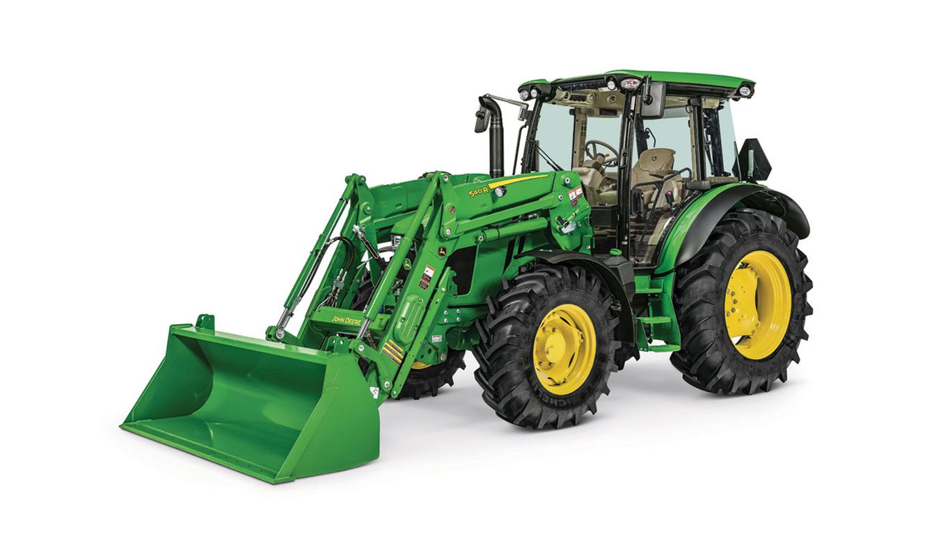
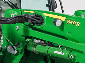
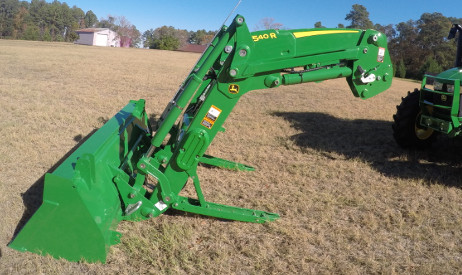
540R Loader
- John Deere
- Agriculture
Key Features & Specs
- Increased lift capacity
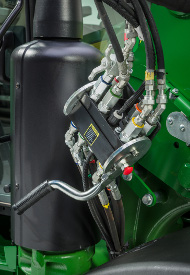
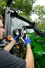
- Seat-mounted loader joystick for optimum control, visibility and comfort
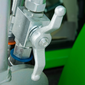
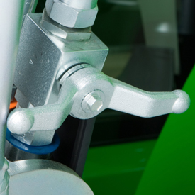
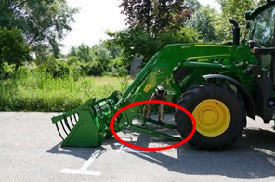
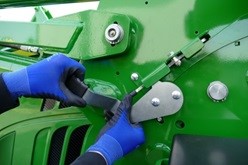
- Remote Implement Unlatch
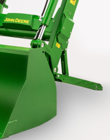
- Automatic mast latch to easily attach/detach loader
- Lift Capacity 3,406 pounds (1545 kg)
- Lift Height 141.85 in. (3.6 m)


Loader
| Leveling configuration | Mechanical Self Leveling (MSL) |
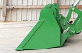
| Bucket weight | 281 kg 619 lb |
| Lift capacity at full height | Measured at pivot (U) 1545 kg 3406 lbMeasured at 800 mm ahead of pivot (V) 1659 kg 3647 lb |
| Lift capacity at 59 in. (1500 mm) | Measured at pivot (W) 1951 kg 4301 lbMeasured at 800 mm ahead of pivot (X) 1804 kg 3977 lb |
| Boom breakout force | Measured at pivot (Y) 2400 kgf 5291 lbfMeasured at 800 mm ahead of pivot (Z) 1950 kgf 4299 lbf |
| Bucket rollback force capacity | At maximum height (VV) 1690 kgf 3725 lbfAt 59-in. (1500-mm) lift height (XX) 2668 kgf 5882 lbfAt ground-level line (ZZ) 2521 kgf 5558 lbf |
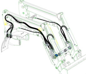
| Dimensions | Maximum lift height (A) 3604 mm 141.85 in.At full height - bucket level(B) 3364 mm 132.44 in.At full height - bucket dumped (C) 2570 mm 101.18 in. |
| Digging depth (H) | 111 mm 4.37 in. |
| Reach | At maximum height (D) 884 mm 34.08 in.At ground level - bucket level (F) 2427 mm 95.55 in. |
| Bucket angle | Dump angle, degrees (E) 64.64 degree (angle)Rollback angle, degrees (G) 46.8 degree (angle) |
| Cycle times | Loader raise, seconds 3.72 secondsLoader lower, seconds 2.79 secondsBucket dump, seconds 2.13 secondsBucket rollback, seconds 2.13 seconds |